When you first get in to Cold Cathode light painting your ambitions will be small. You’ll be impressed when you’ve finally worked out how to take something that normally fits inside your souped-up computer and turned it in to something that works in an abandoned warehouse late at night.
")
The kit usually contains at least one ‘light bulb’, a transformer of some kind, an on/off switch and a mile of cable and connectors to make it work inside your PC. Simply snip off the connectors and attach a 12v power source – usually 8 AA batteries, and hey presto you have a mobile light. At this point most people mount them on the stick with a paint roller handle so you can spin it around. The results are never pretty but they work perfectly.

At some point you’ll realize that you’ve got too many of these. You’ve got the one with the red and blue strips, the one with the green and white, the one with the white and green and so on. Wouldn’t it be easier you wonder, if you put lots of lights on the same stick? And maybe you can get funky and add some blinking lights too? There’s nothing clever about this, just a lot of duct tape and wires to plug and unplug in to the transformer when you want to swap colors.

Three choices of color is simply not enough variation for you though. So you upgrade. Only this time you do it with style. Rather than just a stick with roller brush handle, why not add a proper sturdy handle and a bird feeder so you can add wire wool burning to the tool’s repertoire? It’s still a lot of wires though, and in the dark, that’s not easy to play with. Surely, there’s a better way?

Let’s build the Mega Light Wand 2000. 12 tubes of cold cathode light. 2 tubes of blinking LED lights. All independently switchable. On a frame robust enough to withstand urban warfare. (No fire though).
False Start 1: The DC Myth
Take 3 ft of black PVC tubing and cut in down the middle. This gives you your new ‘stick’. We’re going to drill holes in to so the lights are glued on one side, but all the electronics are on the rear out of harms way.
Those electronics are shown below. We have the power supply, a main on/off switch, one single transformer (sometimes called an inverter), the lights and a multi-position rotary switch used to activate just one light at a time.

Next to each device you’ll see their electronic symbol. You’ll need this for reference when you look at the main wiring diagram.

And what a thing of beauty it is. The power flows from the battery, passes through the on/off switch and in to the transformer. From here the rotary switch can direct the current to any one of the 6 lamps making up the top half of the Mega Light Wand 2000.
Only it doesn’t quite work. All 6 lamps glow slightly, with the one activated by the switch working perfectly.
Clearly, what is happening here is that some of the current is bleeding back in to the lamps along the return wire. That’s simple to fix. We just add a small diode and it all works.
Except it still doesn’t. Something is still causing the lights to glow. Having slept on the problem it finally dawned on me. The above diagram assumes that DC current from the battery is somehow being transformed in to lower DC voltage by the transformer. A quick test with the volt meter shows that this isn’t the case. The transformer you get with the cold cathode kits is actually an inverter. It takes 12v Direct Current and turns it in to a variable Alternating Current ranging from 300 volts to 1200 volts. That’s not a typo. Let me say it again, one thousand two hundred volts. Wow.
Well that explains how I burnt my finger by holding the wire!
False Start 2: The Infinite Power Myth
OK, let’s rip apart bits of this and start again. the main change is going to be replacing the rotary switch with 12 Double Pole Double Throw (DPDT) switches. Let me explain that bit. A double pole switch means it’s one that rather than switching one wire like the on/off switch (SPST), it toggles two wires in unison. The double throw means it doesn’t actually have an off position. Rather it has two on positions just like the switches top and bottom of your staircase at home. We don’t actually need that feature for this toy, but it’s really hard to come by Double Pole Single Throw (DPST) switches. No worries, we’ll simply not wire up one of the terminals.

I’ve used the symbol for DPST rather than DPDT to keep the diagram simple.

Alright, this is still cool. There’s lots more switches and that’s always cool right? They’re not a bow-tie but they’re pretty cool.
Except that once again, the damned thing doesn’t work. After a lot of head scratching and swearing, and a small amount of drinking, I discover that the problem with this is that there’s simply too much wire.
There’s something about the current generated by the inverter that means it fades fast. It exits the inverter at an average of 600 volts. Twelve inches later and it’s dropped to 400. Add a few bits of solder, the almost unmeasurable resistance of the switches and it drops to zero. Yes zero. Somehow, long wires and solder generate enough sinks that the voltage can’t make it to the end of the wire. Originally, the design was one transformer, two rotary switches and 12 lights. Now, it’s one inverter, 12 switches and 12 lights. And it still doesn’t work.
False Start 3: The kitchen Sink Solution
We’re going to use the same components as last time. Same lights, power, switches, everything. Only this time, rather than just one inverter, we’re going to use six. I’m sure you’ve noticed in the wiring diagram that the inverter has two output terminals and we’ve only been using one. Let’s fix that.

And it works! 12 stunningly beautiful lights all independently switched by a control panel that a Sci-Fi movie would approve of.

I’ve not mentioned this yet, but in addition to the 12 cold cathode lights, I’ve also added 2 LED strips. Wiring the strips is easy. I can’t be bothered to tell you how I did it, so instead follow the instructions I started with from The Light Master, Mr {tcb} himself. I actually took several steps beyond this tutorial – that’s just the kinda chap I am.
You’re looking at the rear of the 3rd generation MLW2000. The central switch on the left is the on/off. The outer rows of 12 switches control the cold cathode lamps. The two inner switches at the center control the power to the LED lights. The four push buttons on the right, control the speed and sequence of the LEDs. The batteries are just out of shot on the right.

And this is the front.
And I’ve just discovered that it doesn’t work. Damnittohell.

Only when photographing it for this blog did I notice that the bottom 6 lights are not fully illuminated. There’s 2 inches of unlit cathode at the left of the picture. I was more than prepared to ignore this. I’ve spent almost 2 whole weekends building this damned thing, 2 inches can be excused.
But there’s a worse problem. The Sci-Fi control panel at the back is worse than useless. As a user interface it totally sucks. In the dark, when rushed, when the model is getting goose bumps, the interface is just not intuitive. I frustratingly couldn’t switch the right lights on and off in a timely manner.
Winning! Version 4.
And so another total rebuild was ordered. The lights are not working at full power because the cable is at the extreme end of the inverters’ tolerance. Enough power entered the lamp, but by the time it had traveled the extra 12 inches to the base, it had run out of juice. The solution is to move the inverters and switches as close to the lamps as possible. To remove as much cable as possible. To make every cable as short as humanly possible.
At the same, a new interface is needed. So I’ve decided to move the switches to the front of the wand, directly in line with the light they activate. The main power on/off I’ll leave at the back where it can be reached with ease.

Here’s what you’re looking at. Firstly, it’s wired the same as the diagram above, with the components rearrange for shorter cables. On the left you have the main on/off switch. Then the battery holder, and then the 3 inverters for the top 6 cold cathode lights. The power flows from these inverters in to DPDT switches that are 2 inches away. In the center are the circuit boards for the LED strips, and then the whole pattern repeats itself for the remaining 6 cold cathode lights.

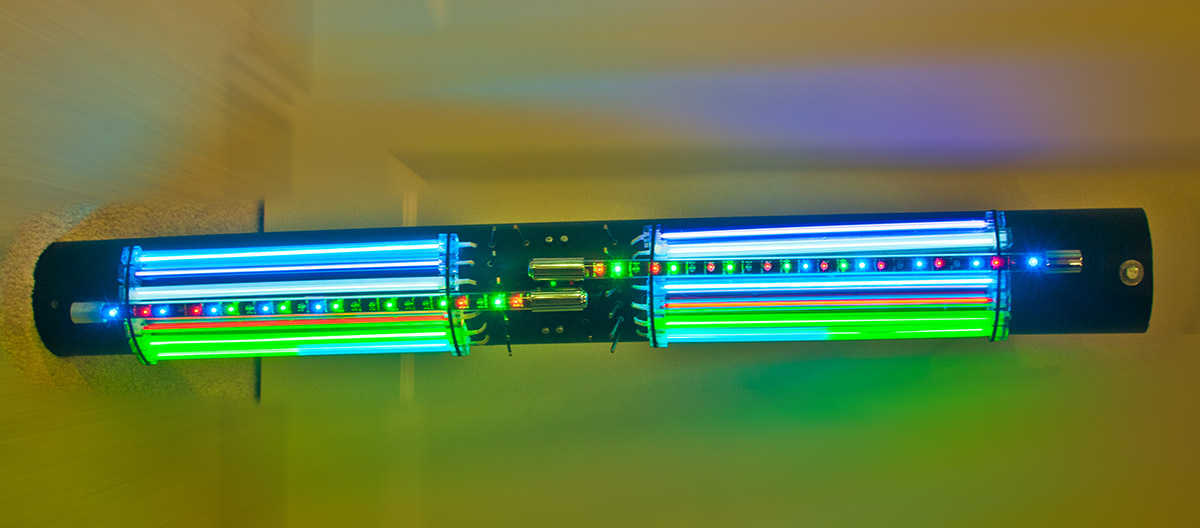
This is the front. you can see the switches in the middle next to the lights they operate. The lamps are all glued on to the tube using a hot glue gun. When trying the wand out, I discovered that there’s just enough flex in the tubing to weaken the glue. And so I’ve added cable ties to provide that little bit of extra security.
And here it is. the Mega Light Want 2000 version four. Feel the glory. Bathe in awe.

Two banks of cold cathode 12 inch tubes in purple, white, blue, red, green, and combination cyan and green.
Two 18 inch strips of randomly rotating LED lights.
One handle to spin it around with.
Shame it’s so damned heavy but as my beautiful wife says, it is groovy.
Come on, talk to us!